TCP/IP Shortcuts for beginners

Data Communication
Data communication means the exchange of information between two or more devices using some transmission medium.
Effectiveness of Data Communication Layer: (DATJ)
- Delivery, 2. Accuracy, 3. Timeliness, 4. Jitter
Components of Data Communication
- Message, 2. Sender, 3. Receiver, 4. Transmission Medium, 5. Protocol
Data Representation
- Text, 2. Number, 3. Images, 4. Audios, 5. Videos
Data Flow
- Simplex, 2. Half Duplex, 3. Full Duplex
Network Criteria (PRS)
Performance →
a. Throughput
The throughput is a measure of how fast we can actually send data through a network
Unit: bps
b. Latency
The latency or delay defines how long it takes for an entire message to completely arrive at the destination from the time the first bit is sent out from the source.
Latency = propagation time + transmission time + queuing time + processing delay
Unit: second
Reliability,
Security
What is a network? Interconnection between devices
Network components → 1. Host, 2. Connecting Devices ( Router, Switch, Modem)
Router → Network to Network Connection
Switch → Device to Device Connection
Modem → Data form exchange
Types of Connections → 1. Wired, 2. Wireless
Wired Connection → 1. Point to Point, 2. Multi-point
Topologies → 1. Bus, 2. Ring, 3. Mesh, 4. Star
Accessing the Internet
Using Telephone → Dial-up and DSL
Using Wireless Network → point-to-point WAN
Using Cable Network → Through Cable
Direct Connect to the Internet → ISP
Switches →
Circuit Switched Network
Packed Switched Network
Two popular Data Communication Models:
OSI → 1. Application, 2. Presentation, 3. Session, 4. Transport, 5. Network, 6. Data-link, 7. Physical
TCP/IP → 1. Application, 2. Transport, 3. Network, 4. Data-link, 5. Physical
Two principles for all protocols:
First principle: Each layer needs to work on two opposite tasks.
Second principle: Each layer must be identical between the source and destination
Addressing each layer of TCP/IP:
| Packet | Layers | Address |
| Message | Application | Name |
| Segment/ User Datagram | Transport | Port Number |
| Datagram | Network | Logical Address |
| Frame | Data-link | Data-link Address |
| Bits | Physical | - |
Lacks of OSI Model Success:
To replace the infrastructure from TCP/IP to OSI model, it needs a lot of time and money,
Services are not fully described in the presentation and session layer of the OSI model and
Performances are not high enough to attract ISOC to switch TCP/IP to the OSI model.
There are 4 signals:
Periodic Analog Signal,
Non-periodic Analog Signal,
Periodic Digital Signal
Non-periodic Digital Signal
Signal Basics:
Bandwidth: The bandwidth of a composite signal is the difference between the highest and the lowest frequencies contained in that signal. Unit: Hz.
$$B = F_h - F_l$$
Bit Rate: The number of bits transferred per second is called bitrate. Unit: bps
$$number \space of \space bits = log_2 (bit \space level)$$
Bit length = propagation speed * bit duration
The non-periodic digital signal can be converted to as non-periodic analog signal.
Transmission of Digital Signal
Baseband:
Baseband transmission means transferring digital signal to digital signal using a low-pass channel.
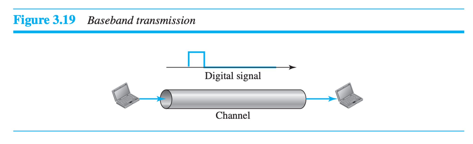
Case 1. Low Pass Channel with Wide Bandwidth
Case 2. Low Pass Channel with Limited Bandwidth,
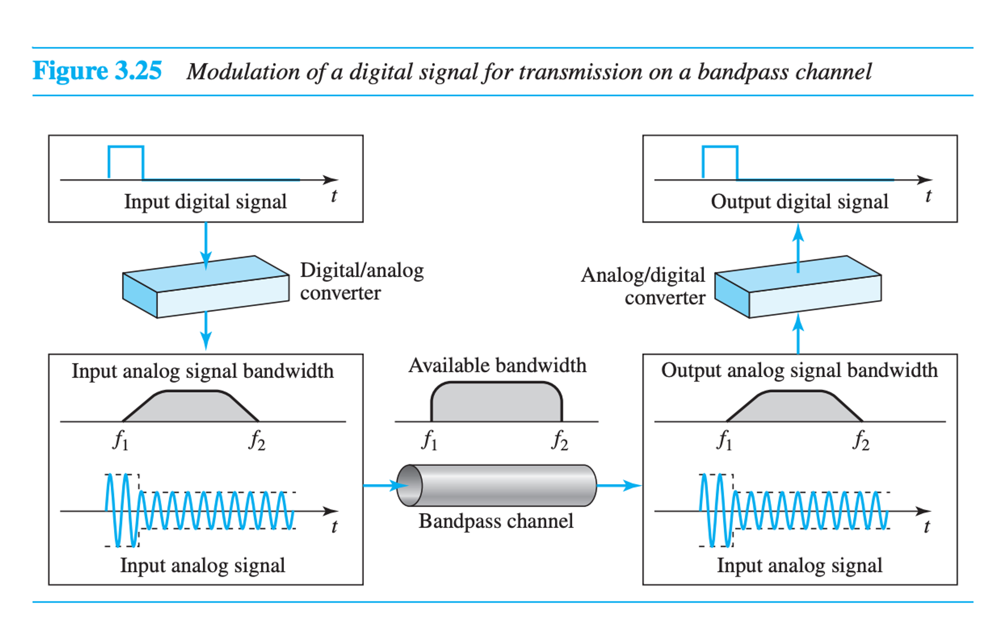
Broadband:
Broadband transmission means converting digital signal to analog signal in the sending end using modulation, and in the receiving end, it converts analog signal to digital signal through the band-pass channel.
Transmission Impairment:
Attenuation (loss of energy),
loss of power (unit: dB)
$$10log_{10}\frac{p_2}{p_1}$$
Distortion (Changes in shape)
Noise
Type of Noises:
thermal: the random motion of electrons in a wire, which creates an extra signal.
Induced: comes from sources such as motors and appliances.
Crosstalk: the effect of one wire on the other
Impulse: a spike (a signal with high energy in a very short time) that comes from power lines or lightning.
Signal-to-Noise Ratio (SNR):
to find the theoretical bit rate limit, we need to know the ratio of the signal power to the noise power. The signal-to-noise ratio is defined as,
$$SNR = \frac{average\space signal \space power}{average \space noise \space power}$$
A high SNR means the signal is less corrupted by noise; a low SNR means the signal is more corrupted by noise. Because SNR is the ratio of two powers, it is often described in decibel units,
$$SNR_{dB} = 10 log_{10}\frac{average\space signal \space power}{average \space noise \space power} = 10 log_{10}(SNR)$$
Data Rate Limits:
A very important consideration in data communications is how fast we can send data, in bits per second, over a channel. The data rate depends on three factors:
The bandwidth available
The level of the signals we use
The quality of the channel (the level of noise)
Two theoretical formulas were developed to calculate the data rate: one by Nyquist for a noiseless channel, and another by Shannon for a noisy channel.
Noiseless Channel: Nyquist Bit Rate
$$bitrate = 2 \times bandwidth \times bit \space length = 2 \times bandwidth \times log_2(Level)$$
Noisy Channel: Shannon Capacity
$$Capacity = bandwidth \times log_2(1 + SNR)$$
capacity is the capacity of the channel in bits per second
Note: The Shannon capacity gives us the upper limit; the Nyquist formula tells us how many signal levels we need.
Equations:
Transmission time = (Message size) / Bandwidth
The bandwidth-delay product defines the number of bits that can fill the link
Digital Signal Conversion
Characteristics of Digital Signal Conversion:
Baseline wandering refers to the slow, low-frequency variations or shifts in the baseline or the zero-level reference of a signal.
When the voltage level in a digital signal is constant for a while, the spectrum creates very low frequencies which creates DC Components problem.
Self-synchronization refers to the sync between the receiver’s bits interval and the sender’s bits interval.
Built-in error-detecting capability in the generated code to detect some or all of the errors that occurred during transmission.
Immunity to Noise and Interference
Complexity: A more complex Scheme is costly.
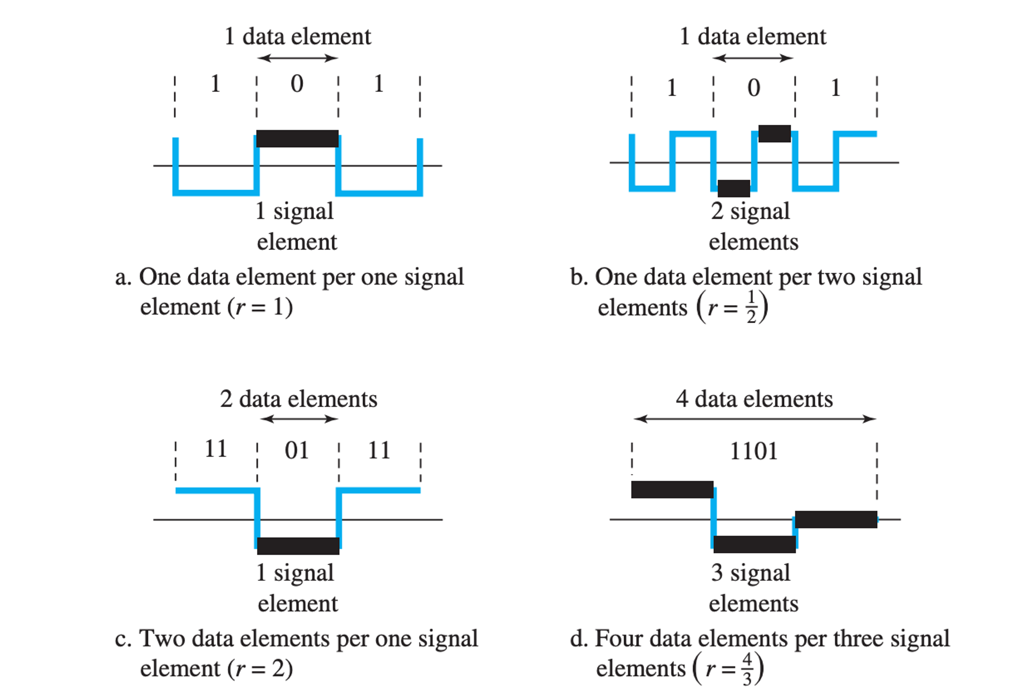
Digital to Digital Data Encoding:
$$r = \frac {data\space element}{signal \space element} = \frac{data \space rate}{ signal \space rate} = \frac{N}{S}$$
Three types of encoding schemes:
Line encoding:
Unipolar: (0, + v / - v)
NRZ:
bit 1 = + v bit 0 = 0
Polar: (+ v, - v )
NRZ-L:
bit 1 = - v
bit 0 = + v
NRZ-I:
bit 1 = change
bit 0 = no change
Biphase:
Manchester:
bit 1 = - v to + v
bit 0 = + v to - v
Differential Manchester:
bit 1 = no transition = no inversion
bit 0 = transition = inversion
Bipolar:
AMI:
bit 1 = transition
bit 0 = 0
Pseudo-ternary:
bit 1 = 0
bit 0 = transition
Multilevel:
2B1Q:
Multitransition:
MLT-3
bit 1 = opposite of last non-zero if the current level is zero 0 if the current level is non-zero
bit 0 = no transition
Bandwidth Table:
| Line encoding name | Bandwidth |
| Unipolar NRZ, Polar NRZ, Polar RZ, AMI, Pseudo-ternary | N/2 |
| Polar Biphase (Manchester, Diffential Manchester) | N |
| 2B1Q | N/4 |
| 8B6Q | 3 N/4 |
| 4D-PAM5 | N/8 |
| MLT-3 | N/3 |
Block encoding: mBnB
- 4B/5B, b. 8B/10B
Scrambling:
B8ZS: (Bipolar with 8 zeros Substuition)
0000 0000 = 000VB0VB V = last non-zero level
B = opposite of the last non-zero level
HDB3: (High Density Bi-polar 3 Zeros)
0000 = 000V (odd numbers of last non-zeros)
0000 = B00V (even numbers of last non-zeros)
Analog to Digital Conversion:
PCM: (Pulse Code Modulation)
Sampling by Nyquist theorem
Quantizing : Delta = (V_max - V_min) / L
Encoding
DM: (Delta Modulation)
Modulator,
Demodulator,
Adaptive DM
Quantizing Error
Digital Transmission Mode:
Serial:
Asynchronous, (stop bit, start bit)
Synchronous (sender and receiver’s clock time = same)
Isochronous (video and audio real-time data)
Parallel
Analog Signal Transmission
Digital to Analog: (Digital Signal + Carrier Signal = Modulated Signal)
ASK
0 = 0 amplitude
level = 2 (BASK)
r = Log( Level)
B = (1 + d) S = (1 +d ) N/ r
PSK
0 = 180 phase
level = 2 (BPSK)
r = Log( Level)
B = (1 + d) S = (1 +d ) N/ r
FSK
1 = Frequency Increased
B = ( 1 + d) * S + 2F
QAM (ASK + PSK)
Use constellation diagram
example: 4 QAM, 16 QAM, 64 QAM
Analog to Analog: (Modulating Analog Signal + Carrier Signal = Modulated Signal)
AM
FM
PM
Bandwidth Utilization
There are 3 multiplexing techniques to utilize the bandwidth:
FDM (Analog Signal)
Frequency Division Multiplexing: Create a composite signal of broad frequencies from input signals. Guard bands are strips of unused bandwidth. In Frequency-division multiplexing (FDM), Channels can be separated by guard bands to prevent signals from overlapping.
WDM (Optical Signal)
Wavelength Division Multiplexing: Create a multiple wavelength signal from input-specific wavelength signals. We use prism for WDM.
TDM (Digital Signal)
Synchronous:
The frame is a combination of time slots. In a frame, number of time slots is the number of input lines.
Frame rate = input data rate
Frame duration = 1 / Frame rate
bitrate = number of input lines * frame rate
To fill empty slots:
Multilevel Multiplexing (100 + 100 → 200)
Multi-slot multiplexing (200 → 100 + 100)
Pulse stuffing ( 190 + 10 → 200)
It uses framing bit as 0 or 1 for synchronization
Interleaving: TDM can be visualized as two fast-rotating switches, one on the multiplexing side and the other on the demultiplexing side. On the multiplexing side, as the switch opens in front of a connection, that connection has the opportunity to send a unit onto the path. This process is called interleaving
Statistical:
It uses no-synchronization
It only takes slots that are filled and inserts an address beside the time slot to identify which slot it is referred to.
In peak time, data lines need to wait for overhead bits.
Spectrum Spreading for Preventing Interference and Spying:
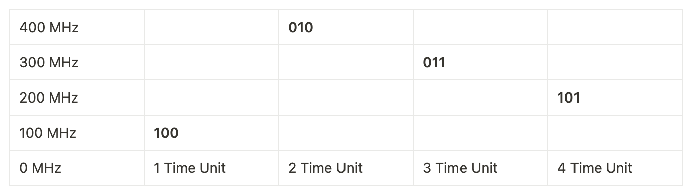
FHSS (Frequency Hopping Spread Spectrum)
It uses a hopping sequence to hop frequencies for transferring data in runtime.
Hopping sequence: 100, 400, 300, 200
Data: 100, 010, 011, 101
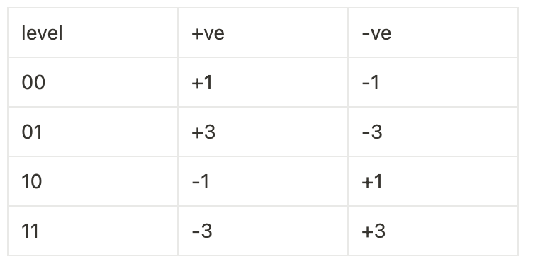
DSSS (Direct Sequence Spread Spectrum)
The signal encoding scheme is Polar NRZ-L. ( bit 1 = -v, Bit 0 = +v)
Sending data: 101
Spreading code: 1011
Spread code: 1011 0100 1011
Transmission Media
Guided Media
Twisted pair:
Ground and Signal
Plastic Cover + Core = UTP, Plastic Cover + Metal + Core = STP
Connected by RJ45
Co-axial:
Outer Layer + Insulator + Outer Conductor + Insulator + Inner Conductor
Connected by BNC
Optical Fibre:
Outer Layer + Dupont Kevlar + Plastic Buffer + Cladding + Core
ST or SC Connector
Mode:
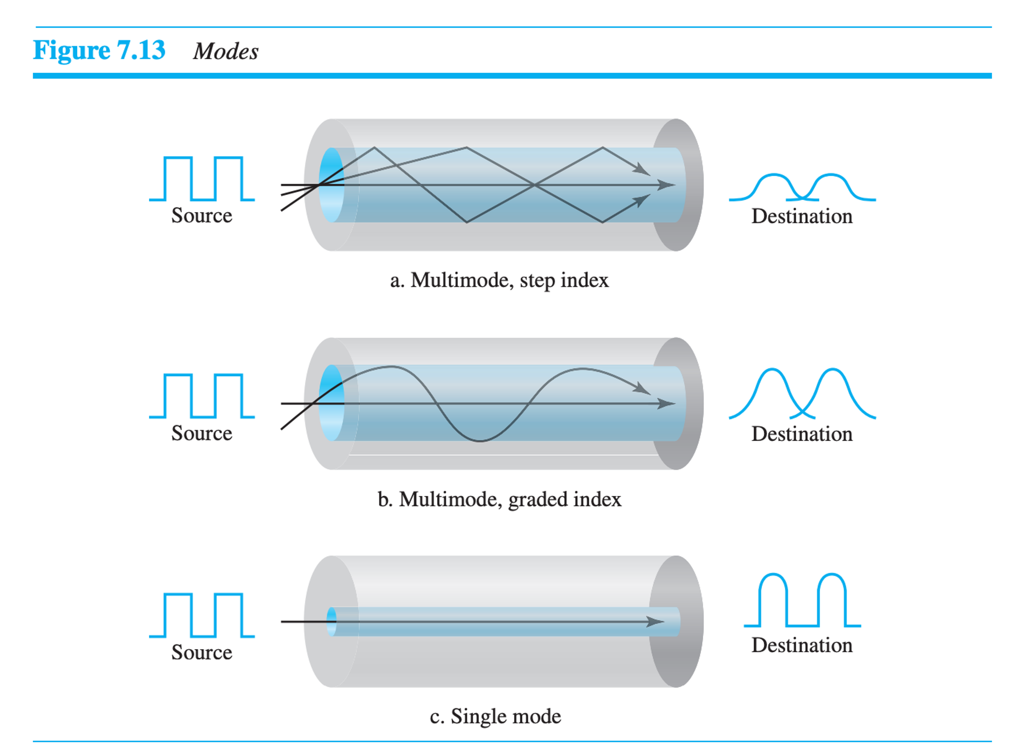
Multimode:
Step index:
The density of the core is constant
Cladding and core are made of the same material
Graded index:
The density of the center of the core is higher and decreases gradually to its lowest at the edge.
Cladding and core are not made of the same material
Single mode:
The critical angle is almost up to 90
The propagation of the beam is almost horizontal
Unguided Media:
Radiowave: (3 KHz - 1 GHz)
Microwave: (1 GHz - 300 GHz)
Infrared: (300 GHz - 400 THz)
Propagation of Radiowave:
Ground propagation:
It used a very low-frequency band
propagates below the lower point of the atmosphere
distance depends on the power of the signal
Sky propagation:
Works by reflecting in the ionosphere
Greater distance traveled by lower output data
Band: High, very high-frequency band
Line of sight:
Antenna-to-antenna data transfer
Band: UHF, EHF
Used in satellite
Antenna:
Omnidirectional Antenna:
One sender to many receivers
Used by radio wave
Unidirectional / Parabolic Antenna:
Send only to one direction
Used by microwave signal
Infrared:
Line of sight propagation
No Antenna needed
Used for shorter distance
Introduction to Data-link Layer
Packet: frame, Address: link-layer address
Connection between: node
Nodes are connected with links. Links are 2 types:
point to point link (DLC sublayer)
broadcast link (MAC and DLC sublayers)
Services of Data-link layer:
Framing
Flow Control (Produced Frames > Consumed Frames)
Error Control
Congestion Control
Link layer Addressing: (48 bits / 6 bytes / 12 hexadecimal digits)
Unicast:
Address: 23:53:29:61:07:F1
Multicast:
Address: 24:54:28:62:08:F2
Broadcast:
Address: FF:FF:FF:FF:FF:FF
ARP (Address Resolution Protocol):
ARP accepts an IP Address from Internet Protocol and maps the address to the link-layer address in the data-link layer.
ARP Packet format:
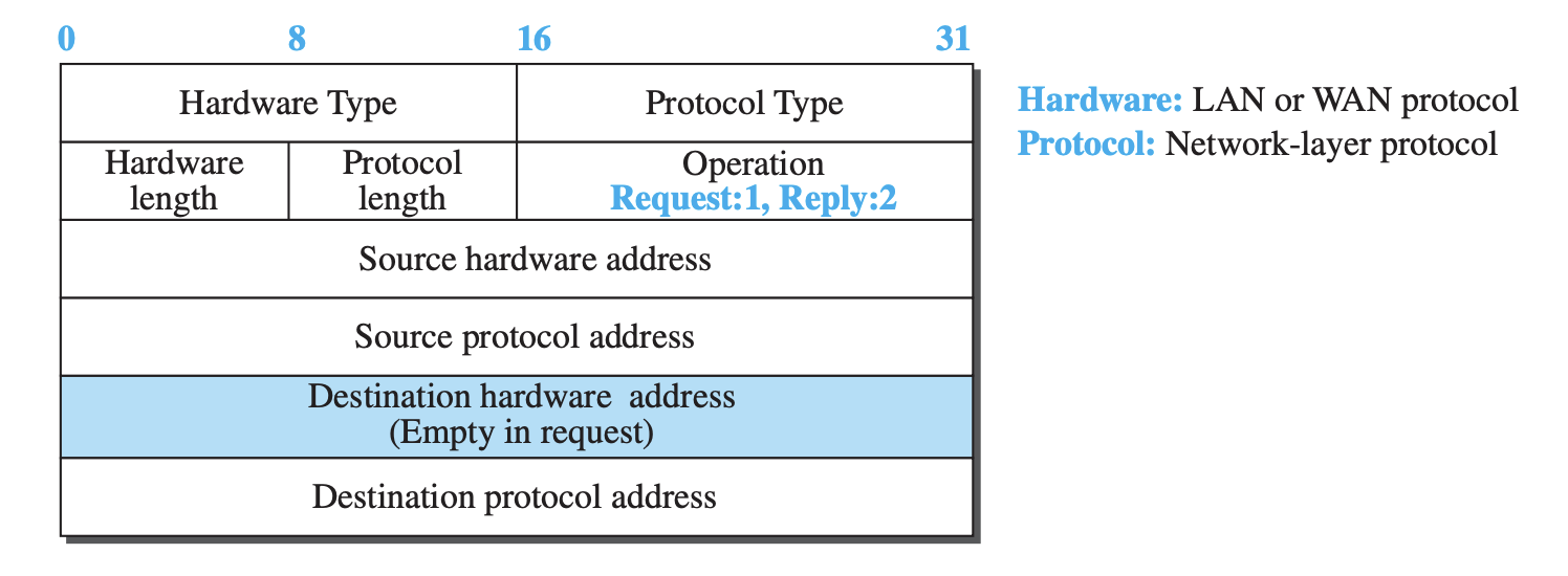
ARP Caching:
Broadcast Link → Store Destination’s link-layer address → Unicast Link
Types of error
1. single error, 2. burst error
Burst length = length (position of first error, position, last error)
There are 2 types of block coding:
1. Dataword, 2. Codeword
The hamming distance can be solved by XORing a two-bit string
Minimum Hamming distance = s + 1 where s = number of errors that can be solved.
CRC and Polynomials:
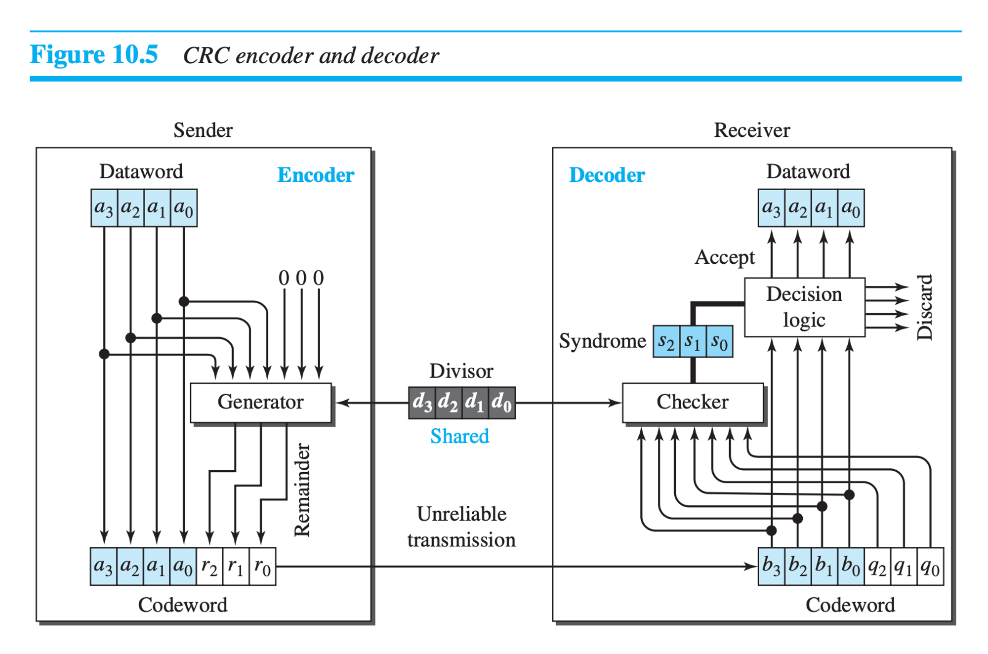
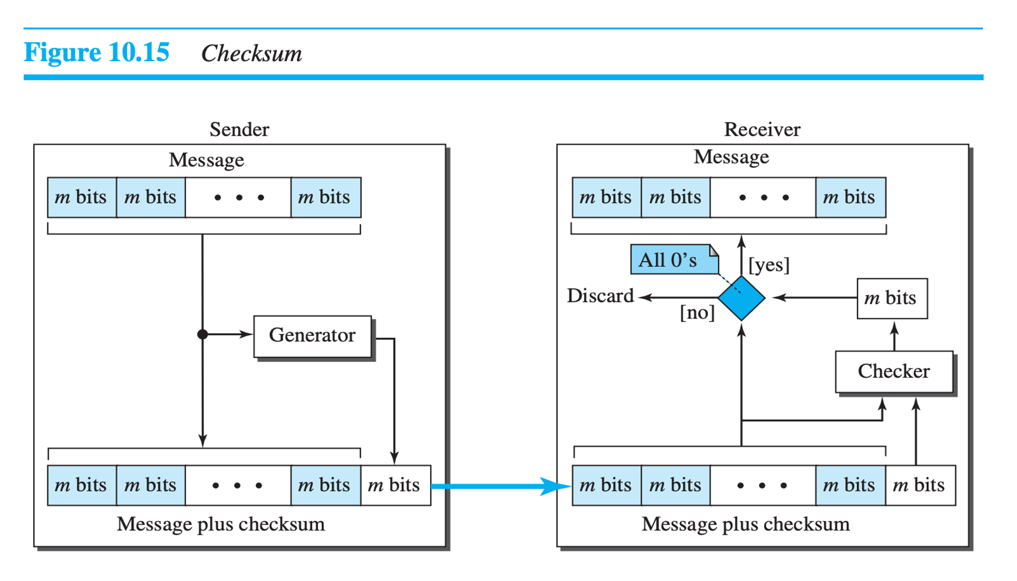
Checksum:
Forward Error Correction Methods:
Hamming Distance
XOR
Chunk interleaving
Chunk interleaving with Hamming Distance
Compounding high and low-resolution packet
Note: CRC is better than Checksum in correcting errors.
DLC (Data link Control) Protocols
Framing: 1. Bit oriented, 2. Character Oriented (byte-oriented)
Byte stuffing: When data has a flag-like byte, we add an ESC byte before it so that the receiver doesn’t end the frame while reading user information. It is used in Character oriented framing
Bit stuffing: The flag is 01111110; while reading user information, it replaces 01111110 with 011111010
Buffer: A buffer is a set of memory locations that can hold packets at the sender and receiver. When the buffer of the receiving data-link layer is full, it informs the sending data-link layer to stop pushing frames. It is used in flow control.
Error Control: This service is provided by a 2-4 byte CRC added to the frame header.
Services: 1. Framing, 2. Flow control, 3. Error Control
DLC protocols can be:
Connectionless oriented: Frames are unnumbered
Connection-oriented: Frames are unnumbered
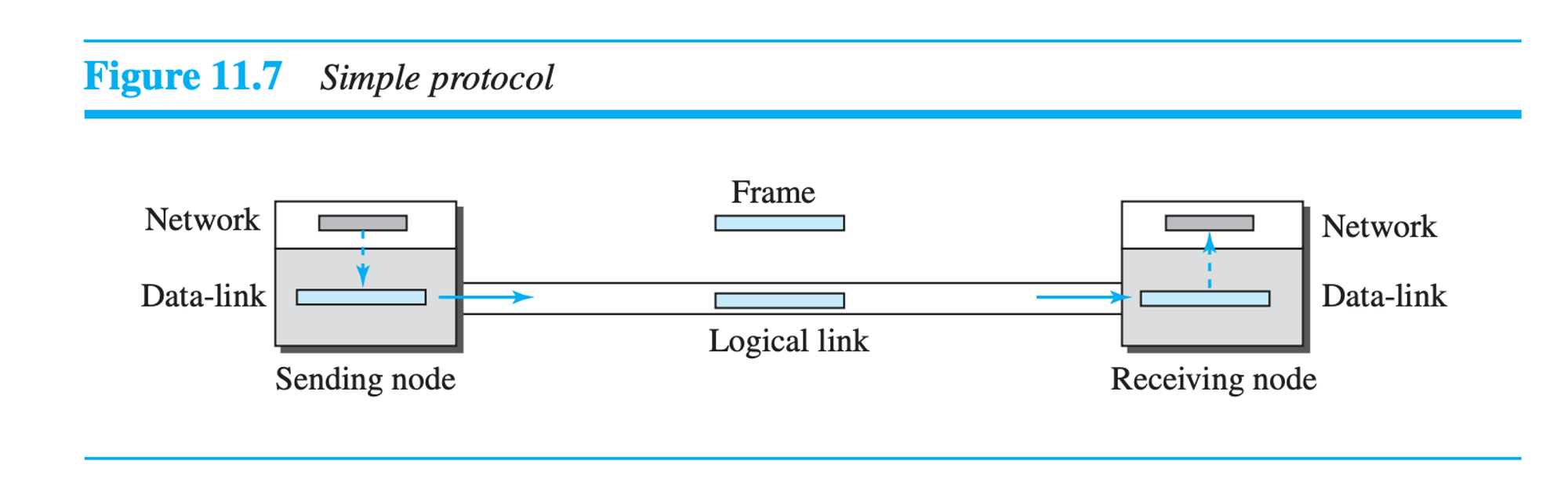
Simple protocol:
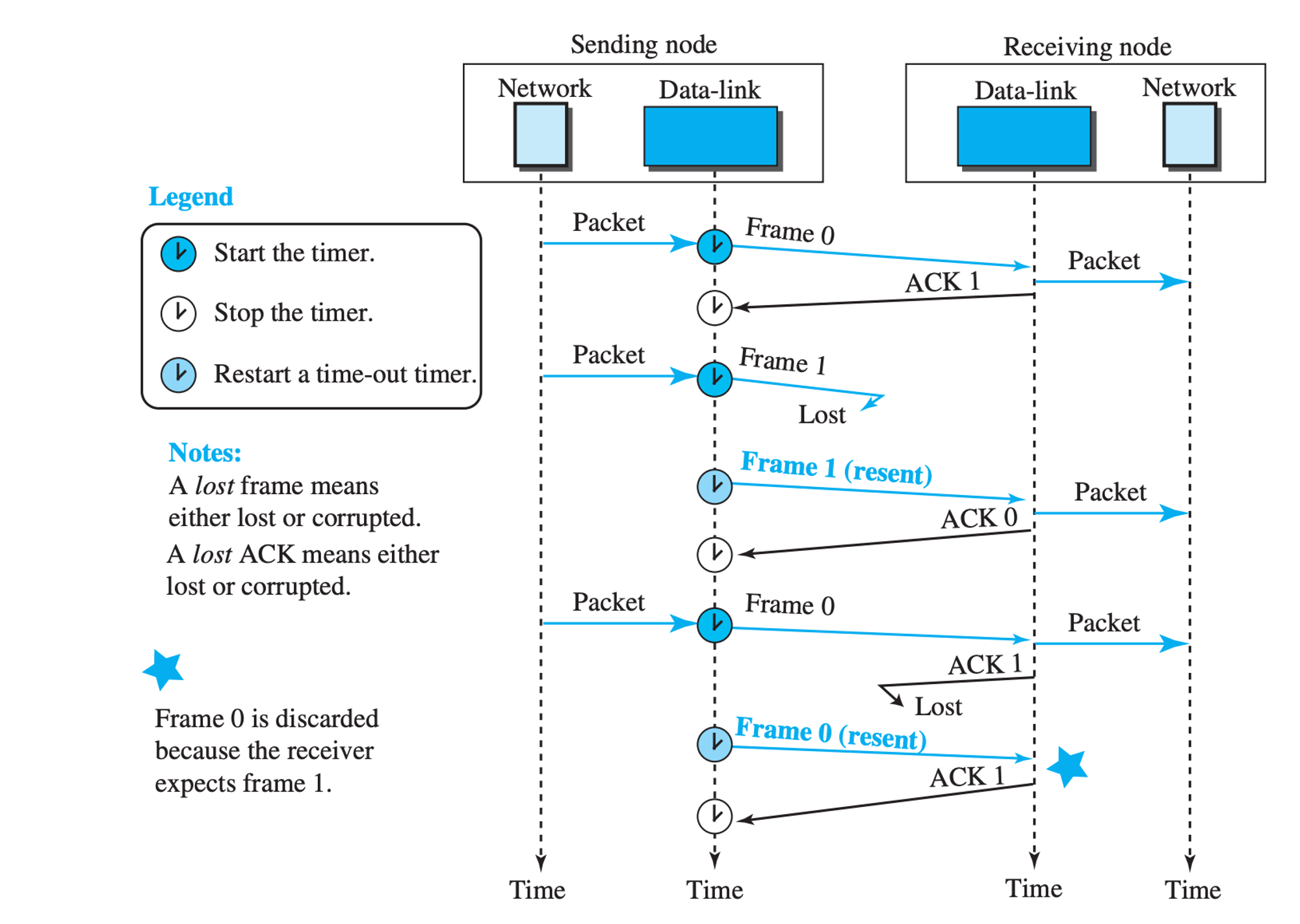
Stop and wait Protocol:
Flow control is provided by sequence number (0,1,0,1,..) and acknowledge number (1,0,1,0,..)
Two states:
Ready State:
Waiting for the packet from the network layer
The sender creates a frame and sends it.
The sender saves a copy of the frame
Blocking state:
If a timeout occurs, the sender resends the frame
If ACK is corrupted, the frame is discarded
else receiver sends error-free ACK to receive the next frame
Piggybacking:
Bi-directional protocol that is sophisticated and costly. The sender and receiver both can send signals and acknowledgment.
HDLC (High-Level Data Link Control Protocol):
Characteristics: 1. Bit oriented, 2. More theoretical than practical, 3. Use Stop and Wait Protocol, 4. Use point-to-point or multi-point links.
Transfer modes:
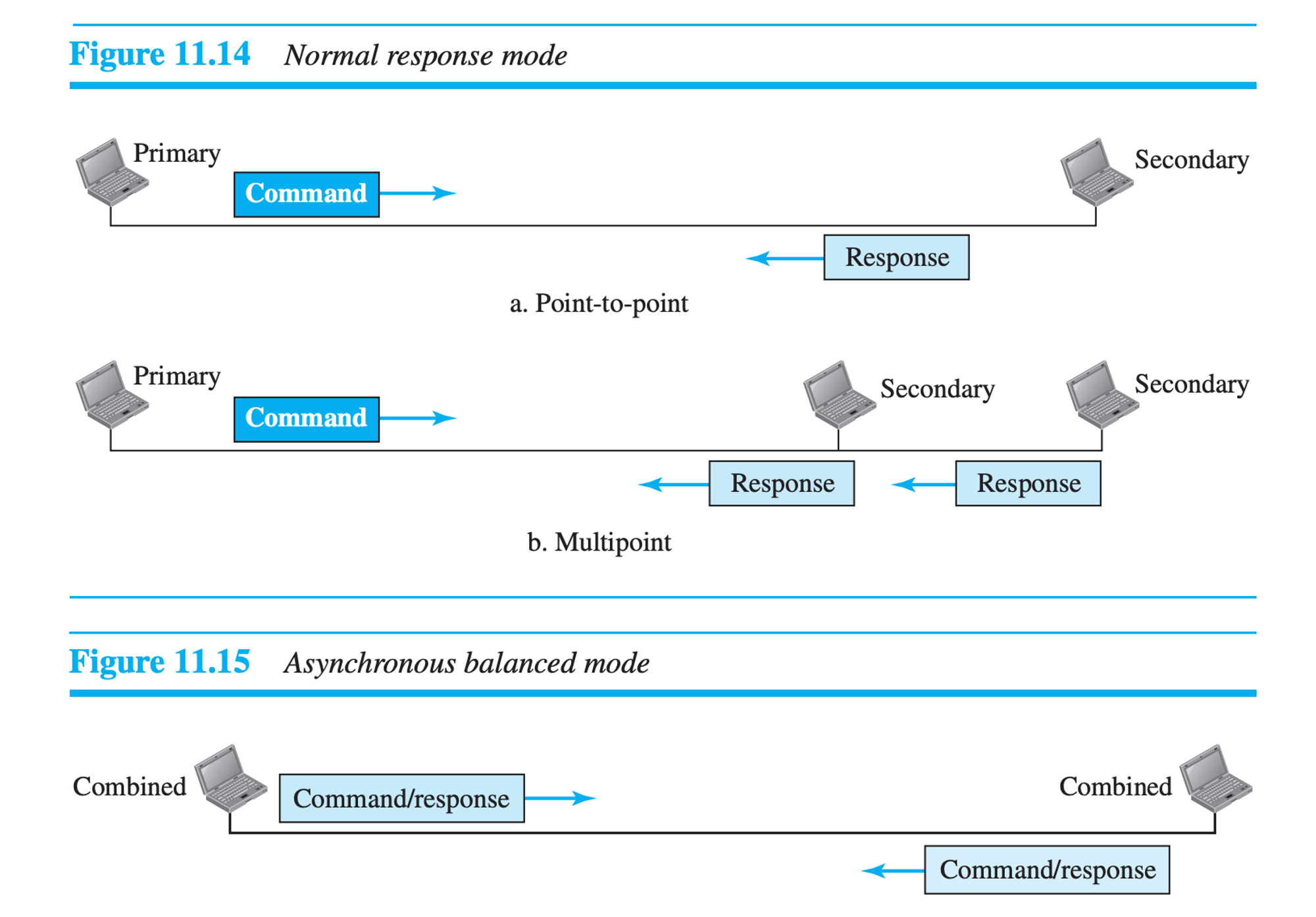
NRM (Normal Response Mode): (Point to point / Multi-point, Unbalanced, 1 Primary Station → Multi Secondary Stations)
ABM (Asynchronous Balanced Mode) (Point to point, Balance)
Framing of HDLC
Information Frame: (Used for transferring data)
| Flag | Address | Control | User Information | FCS | Flag |
Supervisory Frame: (Used for Flow and Error Control)
ACKs: RR (Receive Ready), RNR (Receive Not Ready), REJ (Reject), SREJ (Selective Reject)
| Flag | Address | Control | FCS | Flag |
Unnumbered Frame: (Used for connection establishment and release)
| Flag | Address | Control | Management Information | FCS | Flag |
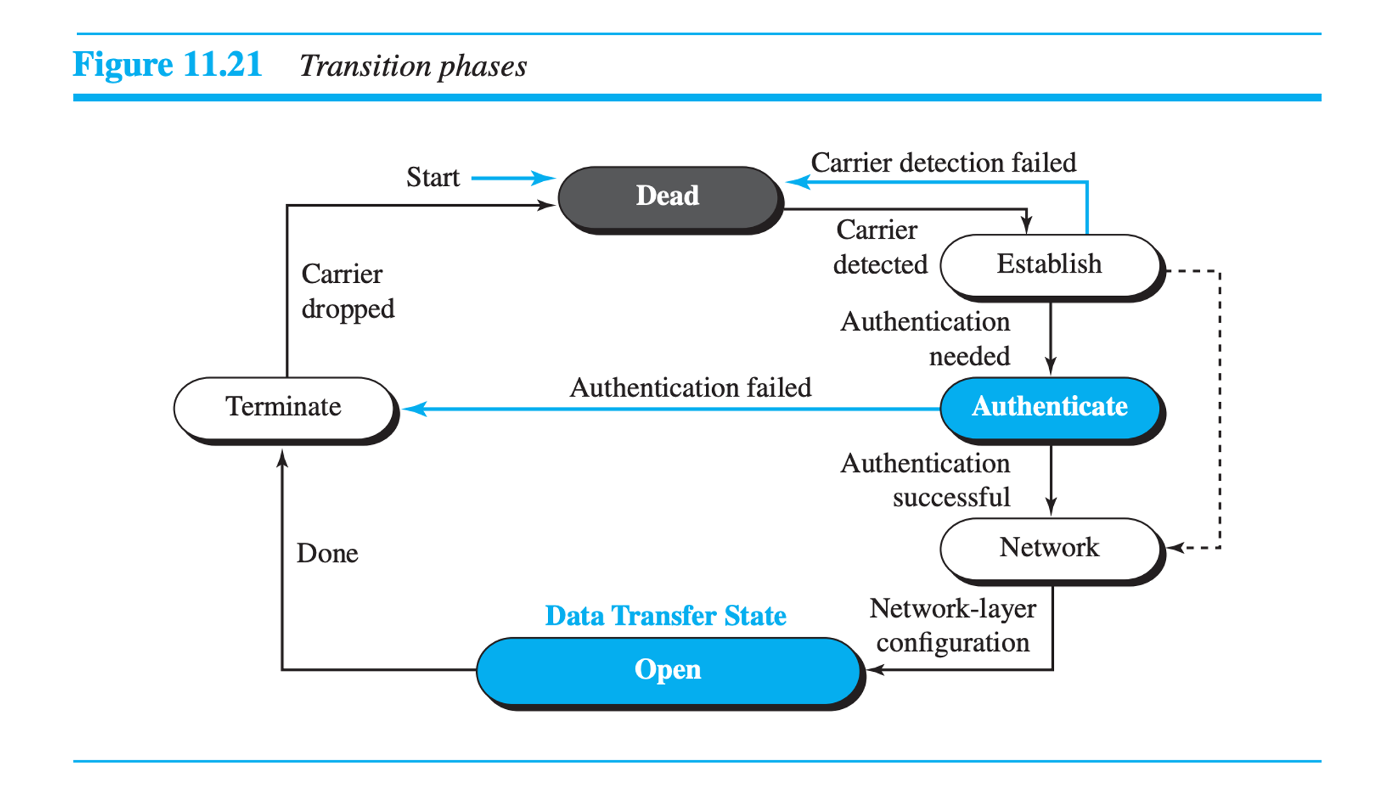
PPP (Point-to-Point Protocol)
Services: 1. Most used protocol, 2. Provide Authentication and network configuration, 3. Error Control.
PPP doesn’t provide flow control.
PPP Framing:
| Flag | Address | Control | Protocol | Payload | FCS | Flag |
| 01111110 | 11111111 | 00000011 | 1-2 bytes | Variable-sized | 2-4 byte CRC | 01111110 |
PPP has created two protocols for authentication: PAP (Password Authentication Protocol) and CHAP (Challenge Handshake Authentication Protocol). Internet Protocol Control Protocol (IPCP) is framed inside PPP framing for carrying IP data packets.
Transition phase of PPP:
MAC Protocols (Media Access Control)
Random Access Protocol:
ALOHA (Advocates of Linux Open-source Hawaii Association): Radio LAN
CSMA ( Carrier Sense Multiple Access): Ethernet
CSMA / CD (Carrier Sense Multiple Access with Collision Detection): Traditional Ethernet of 10 Mbps data rate
CSMA / CA (Carrier Sense Multiple Access with Collision Avoidance): Wireless Network
Control Access Protocol:
Reservation: Device needs reservation before sending data
Polling: One device is the primary station, and others are the secondary station
Token Passing: Networks are organized in a logical ring, and all stations are either predecessors or successors.
Channelization:
FDMA (Frequency Division Multiple Access): The bandwidth of the common channel is divided into bands that are separated by guard bands.
TDMA (Time Division Multiple Access): Stations share timeslots.
CDMA (Code Division Multiple Access): All data are sent by one channel with different codes.
Abbreviations:
ARPANET: Advanced Research Projects Agency Network
TCP: Transmission Control Protocol
IP: Internet Protocol
ISOC: Internet Society
IAB: Internet Architecture Board
ASCII: American Standard Code for Information Interchange
ISO: Internation Organization for Standardization
OSI: Open Systems Interconnection